Harmonic loading
The structure will now be loaded with an external harmonic load, which will cause the structure to vibrate.
A forced vibration calculation can be required to check the response of a building near a railroad or major traffic lane, to check vibrations due to machinery, to verify structural integrity of a floor loaded by an aerobics class,…
Back ground
SDOF harmonic loading
To understand what is going on during the dynamic analysis of a complex structure with frames or finite elements, the forced vibration of a SDOF (Single Degree Of Freedom) system is regarded in detail.
Consider the following system:
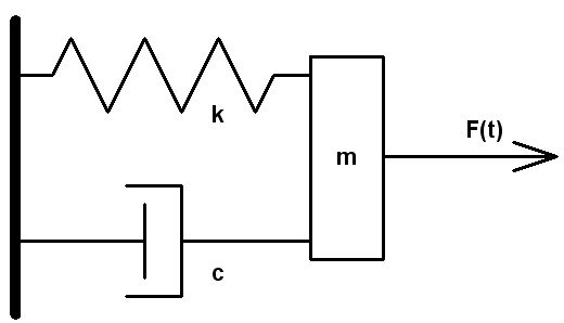
A body of mass m can move in one direction. A spring of constant stiffness k, which is fixed at one end, is attached at the other end to the body. The mass is also subjected to damping with a damping capacity c. An external time dependant force F(t) is applied to the mass.
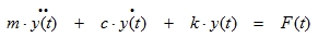
The equation of motion can be written as:
|
(3.1) |
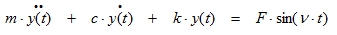
When the acting force on this system is a harmonic load, equation (3.1) can be rewritten as follows:
|
(3.2) |
With:
F = Amplitude of the harmonic load
ν = Circular frequency of the harmonic load
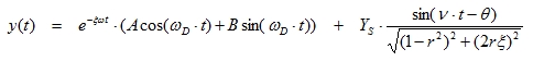
A solution to this equation is the following:
|
(3.3) |
With: The static deflection (3.4)
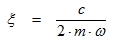 The damping ratio (3.5)
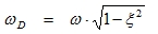 The damped circular frequency (3.6)
|
(3.7) |
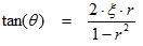
 The frequency ratio (3.8)
The angle θ signifies that the displacement vector lags the force vector, that is, the motion occurs after the application of the force. A and B are constants which are determined from the initial displacement and velocity.
The first term of equation (3.3) is called the Transient motion. The second term is called the Steady-state motion. Both terms are illustrated on the following figure:
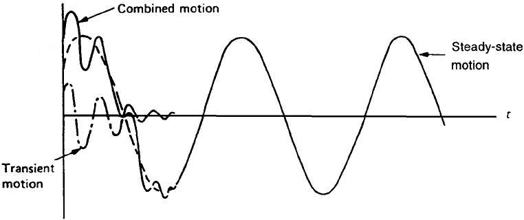
The amplitude of the transient response decreases exponentially ( ). Therefore, in most practical applications, this term is neglected and the total response y(t) can be considered as equal to the steady-state response (after a few periods of the applied load).
Equation (3.3) can then be written in a more convenient form:
|
(3.9) |
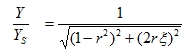
 is known as the Dynamic Magnification factor, because YS is the static deflection of the system under a steady force F and Y is the dynamic amplitude.
The importance of mechanical vibration arises mainly from the large values of experienced in practice when the frequency ratio r has a value near unity: this means that a small harmonic force can produce a large amplitude of vibration. This phenomenon is known as resonance. In this case, the dynamic amplitude does not reach an infinite value but a limiting value of  .
.
The second term in equation (3.1) represents the damping. The damping of the model is defined by the damping ratio.
Let’s remark that that damping can be over ruled by using the non-uniform damping method, where the user is allowed to define the damping of the elements on more precise way. See for more detail the chapter “Damping”.
The logarithmic decrement Λ is the natural logarithm of the ratio of any two successive amplitudes in the same direction. This is illustrated on the following figure:

|
(3.10) |
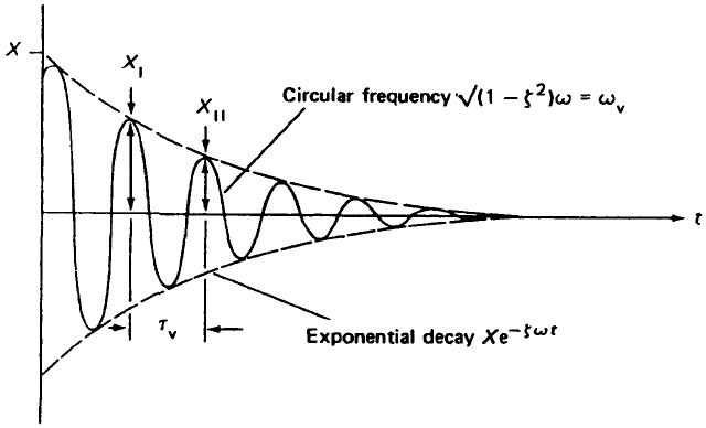
The logarithmic decrement Λ is related to the damping ratio ξ by the following formula:

MDOF harmonic loading
When the loads applied to a structure are sinusoidal, the general equation becomes:
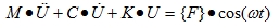
|
This means that more than one node of the structure can be loaded but the frequency of all solicitations should be equal.
The solution which is of interest in this case is the particular solution which describes the stationary state of the structure without taking into account the initial conditions and transient behaviour (this is in contrast with the time dependent solution where one calculates the transient behaviour and eventually when integration time is long enough, finally arrives at the stationary state behaviour).
The stationary state will give a sinusoidal result in each node, with a frequency equal to the applied frequency. The resulting vibration will be in faze with the load when C=0. When C is not zero, there will be a faze shift. The solution is found once more by uncoupling the equations as before. The amplitudes of the harmonic response are determined and given in the output.
Practical used
Harmonic load calculation in SCIA Engineer
SCIA Engineer supports the harmonic calculation in a general 3d environment (composed by 1d and 2d elements)
The Harmonic Load can be inputted after creating a Combination of Mass Groups. This implies that the steps used to perform a Free Vibration calculation still apply here and are expanded by the properties of the Harmonic Load.
Harmonic Loads in SCIA are always defined as nodal forces i.e. a nodal load or a nodal moment. More than one node of the structure can be loaded in a load case, but the frequency of all solicitations is equal to the forcing frequency specified for that load case.
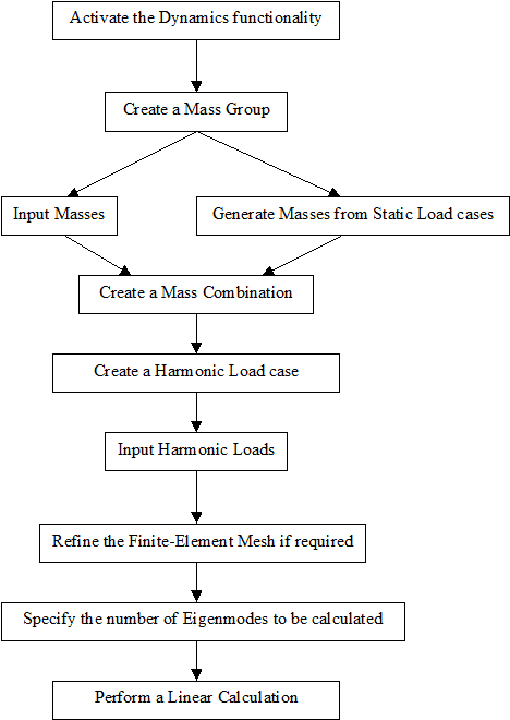
The following diagram shows the required steps to perform a Harmonic Load calculation: